What's New In The 3D Printer World
Prevention is the key
Over the last few weeks there have been posts on social media relating to fires being caused by 3D printers.
As a result there have been comments made on these posts indicating that smoke detectors and fire extinguishers should be used while printing, just incase something should happen. It is basic common sence to have some sort of detector system in a property in general, not just because you have a 3D printer. If you are going to rely on these devices to protect you property while using a printer, is like shutting the gate once the horse has bolted.
What is needed is every prevention measure to be made possible so that the printer will not turn into a fire ball. I cannot guarantee that the printer will not go up in smoke or cause a fire, however doing everything possible to prevent a disaster is better than nothing at all and just sit there with extinguisher in hand poised for that puff of smoke to appear.
I general the power supply for most printers is a switch mode type, as they are cheap to construct and deliver high current for there size.
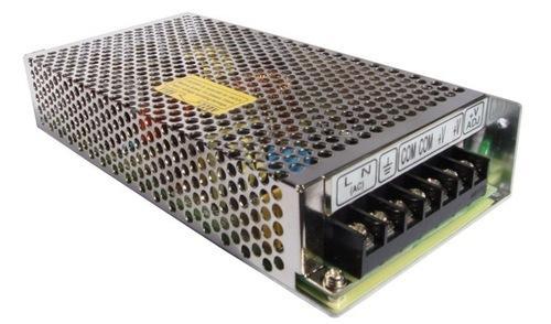
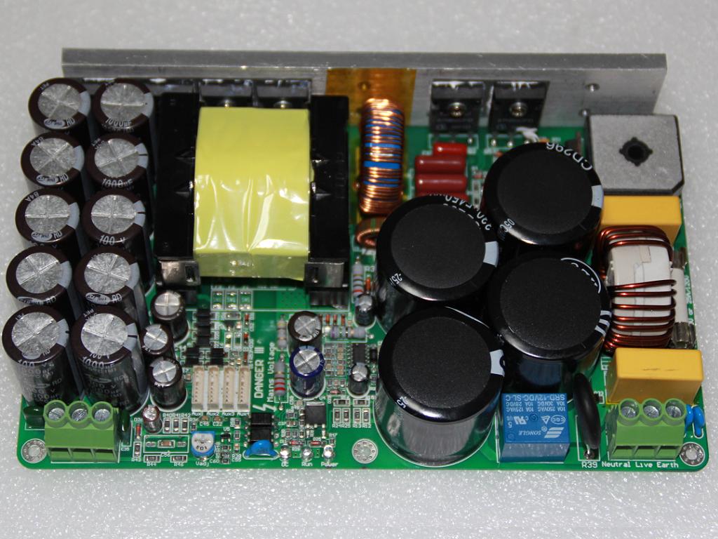
They are also small as there is no transformer used to step down the high AC voltage to the low Dc Voltage required.
They are fused on the AC circuit but normally the DC voltage has little protection which is what I shall address in this post.
There a number of factors that have caused these fires recently.
1 DIY builders following the build instructions to the letter accepting the fact the manual is 100% correct without question.
2 Cables supplied are the absolute minimum gauge required for the printer to run.
3 Controller board connections are under rated for the load required.
4 No fuse protection or inadequate protection.
5 Rushing the printer build process.
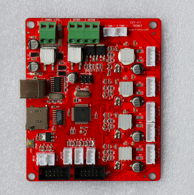
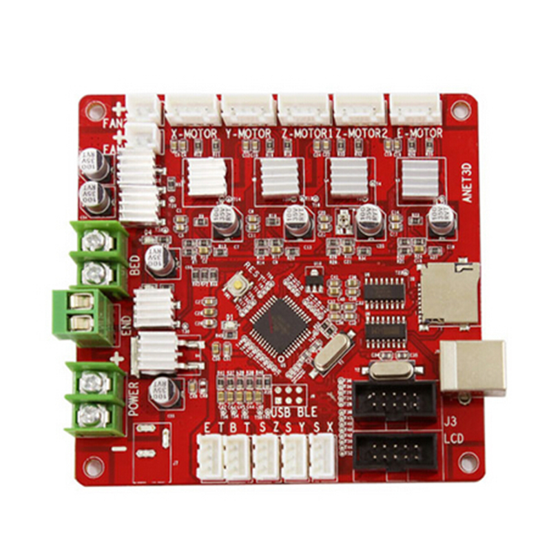
I have had experience in the past where the printer controller shown below fuse holders melting due to the current passing through the electronics,
and melting the PCB track before the fuse has blown.
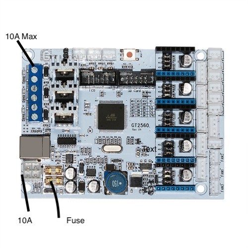
You may ask why would this happen? Well you have to break down the current that is being used on the board. firstly each stepper driver / motor draws between 1.5 to 2 amps.When you add the heated bed and hotend they can draw combined Up to 13 amps at any given point while the printer is running. So with the potential current passing through 10 amp connectors thin copper track something is bound to go wrong, and this is with a board that has fuses onboard.With most boards provided with kits there is no protection of any kind.
There are some simple steps you can take to protect your printer and your home from disaster, but this means you need to rewire the printer from the ground up.Yow will need 7 AWG minimum cable Black and Red preferably with silicone sheathing the same that is used for RC model battery connections.
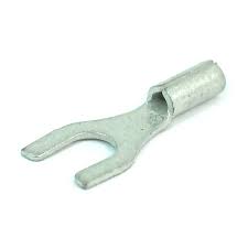
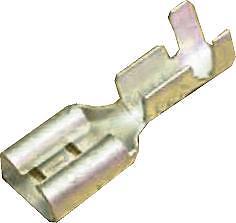
Spade terminals
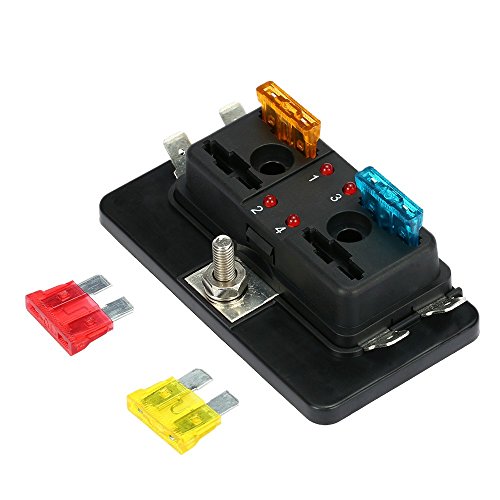
Automotive fuse box
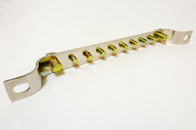
Earth bar
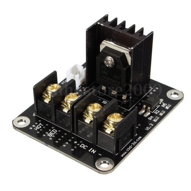
Minimum of 1 external mosfet board for heated bed, however there is nothing to prevent one being used for the hot end.
Soldering iron. I know soldering connectors and tinning the ends of bare cable is controversial however in my opinion this makes the join strong and less likely to seperate.Below is The circuit used on a printer.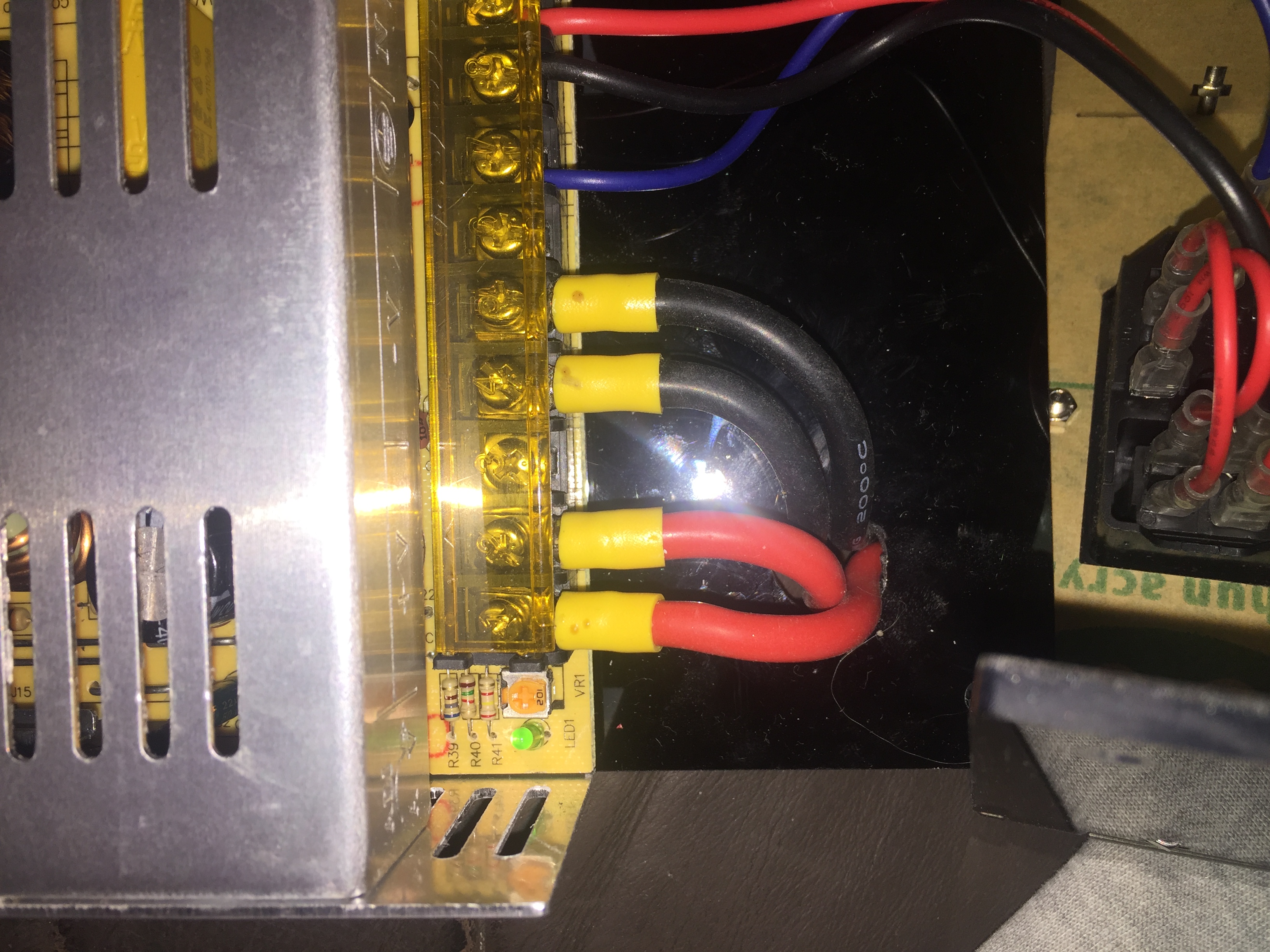
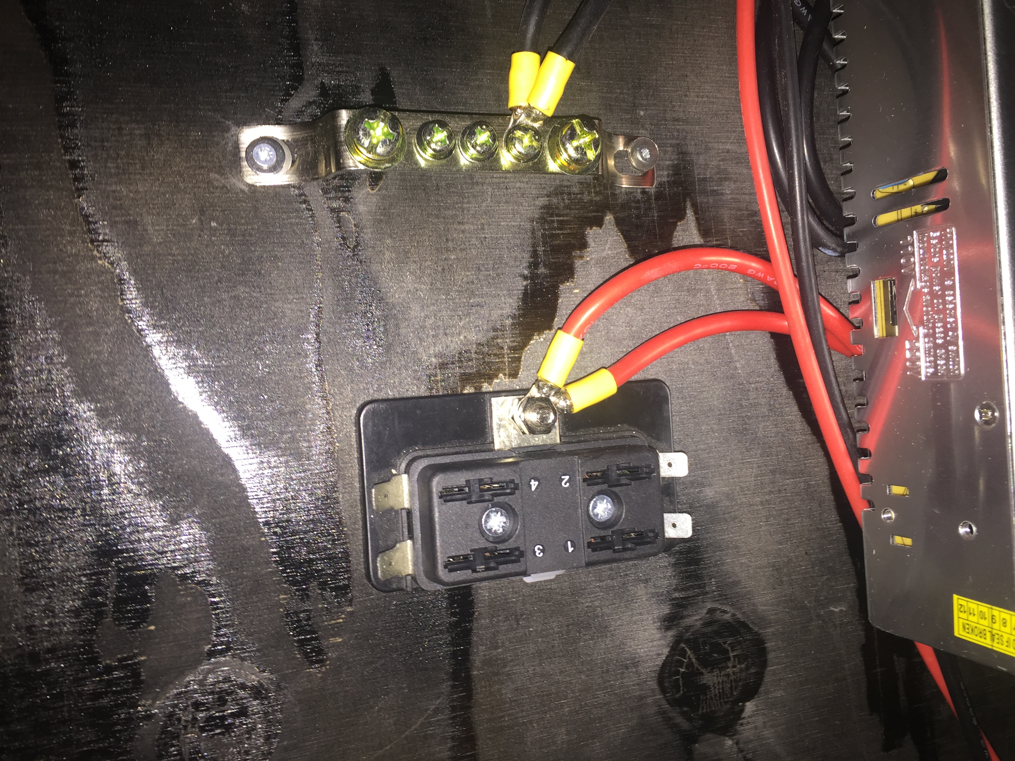
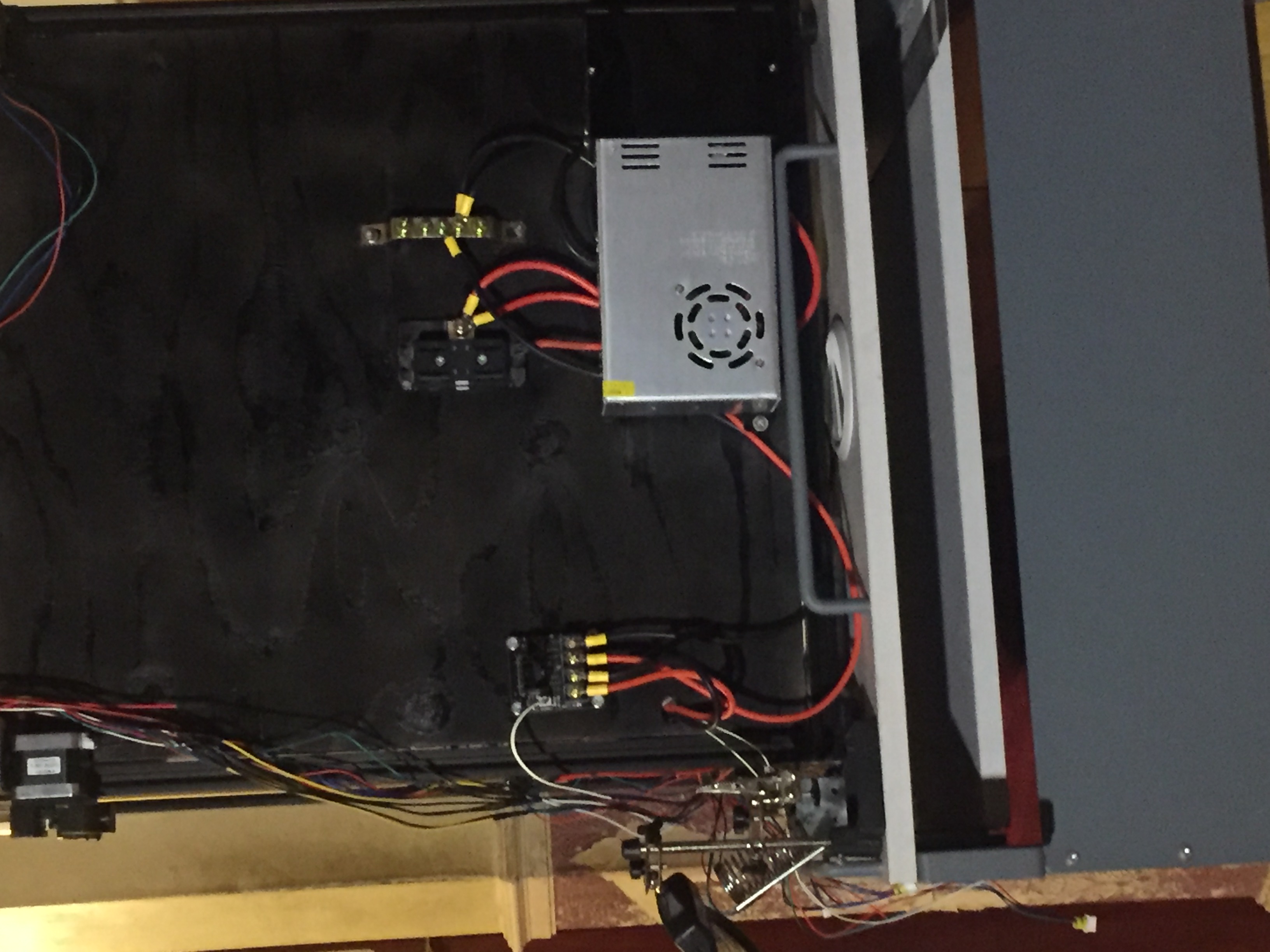
As you can see in the imaged the cables from the PSU to the Fuse panel and earth bar are doubled up. this exceeds the current rating of the power supply. this is optional however means you have no issues with overloading the feed cables. The bottom image is the mosfet connection to the heated bed. While connecting the mosfet to the fuse panel the feed cables to the heated bed were also replaced with the same gauge cables. This can be problematic to do as the heated bed will draw the heat away from the soldering iorn and you will need a large tip to undertake this task.
As the heated bed will take a large amount of current you will need to use a fuse rated at 10 to 15 amps depending on the wattage of the bed.There have been comments stating that the mosfet board is not necessary, however the most compelling reason to use one is to remove the overload situation from the main controller board.
The next thing to connect to the fuse box is the controller you will need a 7.5 to 10 amp fuse depending on how many stepper drivers are connected or you have the hotend still connected onto the main board.
It is unfortunate we have to undertake these types of measures with a brand new printer kit, in the real world this should be done at the manufacturer's, but this is not the case so we have to be proactive to prevent disaster, So whoever you are please make sure your safe, and take the time to make sure your 3D printer is protected from the get go. It is a great hobby and has many uses, but you will only get the results if some effort is made by the end user. Do not take anything on face value is correct. take your time and get it right.

About the author
Comments 3

The bit about not tinning the wire ends is because solder doesn't hold up well, dimension wise, when compressed. The crushed solder heats up, connection gets softer and looser, gets hotter, gets looser still, hotter still.... Soldering a wire is good if the solder is what makes the connection, but not if solder is used to push against in a compression connector. Compress against bare copper (strong, doesn't squish softly) not against solder (lead squishes softly), if you must compress. If you don't need a removable connector, soldering the wires directly to the board can be a good way to go but you have to be pretty good at soldering without messing anything up on the board.